
Introduction of works
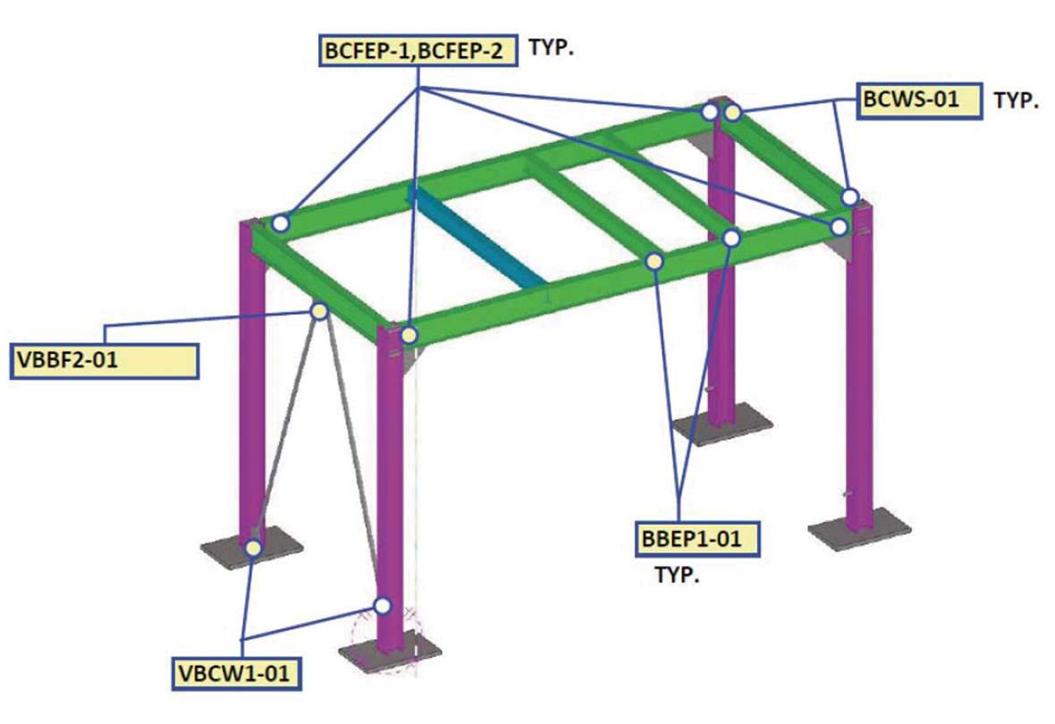
Steel structure node design is a key link in steel structure engineering. It is mainly responsible for determining the connection method and detail construction between each steel member to ensure the stability, bearing capacity and reliability of the whole structure.
In the design process, a variety of factors need to be considered comprehensively. First of all, the mechanical properties, based on the size, direction and point of action of the load borne by the structure, accurately calculate the force at the node, so as to select the appropriate form of connection, such as welding, bolting or riveting, etc., and to determine the specification size of the connection to ensure that the node can effectively transfer the internal force. At the same time, the feasibility and convenience of construction should be considered to ensure that the node structure is convenient for on-site installation and operation to improve construction efficiency and quality. In addition, it is also necessary to pay attention to the durability of the nodes, and take corresponding anti-corrosion and fire prevention measures to adapt to different operating environments. Through careful design of steel structure nodes, the steel components are closely connected and work together to lay a solid foundation for the safety and stability of steel structure buildings or facilities, which plays an important role in industrial plants, high-rise buildings, bridges and many other fields.
计算表
|
CONNECTION TYPE |
VBC2-02_01 |
AISC Manual of steel construction, 9th edition |
REV.0 |
||||
|
|
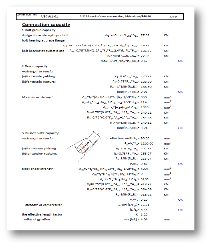
Connection capacity |
|
|
|
|
||
|
|
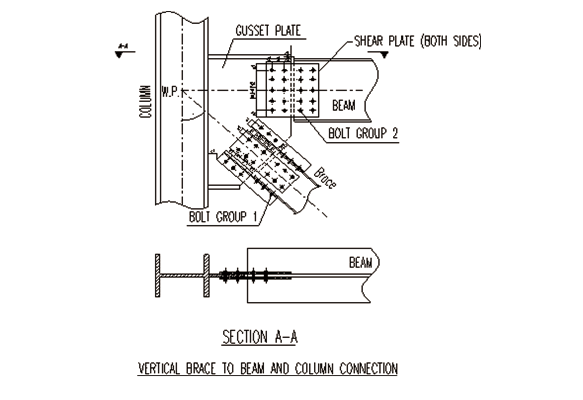
1.Bolts group capacity |
|
|
|
|
||
|
|
(1)at brace flange |
|
|
|
|
|
|
|
|
—allowable slip resistance |
|
|
|
|
||
|
|
|
|
Fa1= |
Fv1*Av1 |
|
|
|
|
|
|
|
= |
113.81 |
KN |
|
|
|
|
—bolt bearing at flange of brace |
|
|
|
|
||
|
|
|
|
Fa2= |
1.2*Fub*Ab |
|
|
|
|
|
|
|
= |
184.41 |
KN |
|
|
|
|
—bolt bearing at gusset plate |
|
|
|
|
||
|
|
|
|
Fa3= |
1.2*Fugp*Ab |
|
|
|
|
|
|
|
= |
483.49 |
KN |
|
|
|
|
—bolt bearing at angle |
|
|
|
|
||
|
|
|
|
Fa4= |
1.2*Fua*Ab |
|
|
|
|
|
|
|
= |
154.31 |
KN |
|
|
|
|
|
|
Fa=MIN(Fa1,Fa2,Fa3,Fa4)= |
113.81 |
KN |
|
|
|
|
|
|
[Ptf/(nr1*nc1)]/Fa= |
0.00 |
|
OK |
|
|
|
|
|
[Pcf/(nr1*nc1)]/Fa= |
0.30 |
|
OK |
|
|
|
|
|
|
|
|
|
|
|
|
(2)at brace web |
|
|
|
|
|
|
|
|
—allowable slip resistance |
|
|
|
|
||
|
|
|
|
Fa1= |
Fv1*Avb1 |
|
|
|
|
|
|
|
= |
227.63 |
KN |
|
|
|
|
—bolt bearing at web of brace |
|
|
|
|
||
|
|
|
|
Fa2= |
1.2*Fub*Ab |
|
|
|
|
|
|
|
= |
184.41 |
KN |
|
|
|
|
—bolt bearing at gusset plate |
|
|
|
|
||
|
|
|
|
Fa3= |
1.2*Fugp*Ab |
|
|
|
|
|
|
|
= |
483.49 |
KN |
|
|
|
|
—bolt bearing at shear plate 1 |
|
|
|
|
||
|
|
|
|
Fa4= |
1.2*Fusp1*Ab |
|
|
|
|
|
|
|
= |
386.79 |
KN |
|
|
|
|
|
|
Fa=MIN(Fa1,Fa2,Fa3,Fa4)= |
184.41 |
KN |
|
|
|
|
|
|
[Ptw/(nrb1*ncb1)]/Fa= |
0.00 |
|
OK |
|
|
|
|
|
[Pcw/(nrb1*ncb1)]/Fa= |
0.26 |
|
OK |
|
|
|
|
|
|
|
|
|
|
Related Main Business

Norgener FGD and Fabric Filter

TanjungBin Power Plant, Malaysia

Cameron LNG Liquefaction Project


Xiamen Yunding Road Bicycle Expressway Demonstration Section

Abu Dhabi Airport International Terminal

Shenzhen Museum of Contemporary Art and Urban Planning Exhibition Center
Let's
Contact us!

Immediate Consultation
Address: Building 802, Guanggu Wisdom Garden, No.7, Financial Port Road 1, Donghu High-tech Zone, Wuhan
Social Media

Official